
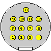
| Pin Number |
Pin Name |
Description (may be empty) |
| 1 | CH-REQH | Request output to changer; Low : Request |
| 2 | GND | |
| 3 | Vcc | +12V |
| 4 | CH-CON | Changer control out; High : Operation mode Low : Standby |
| 5 | CH-MUTE | Mute request from changer; High : Mute |
| 6 | AGND | Audio Ground |
| 7 | CH-RST | Reset output to changer |
| 8 | R | Audio right channel |
| 9 | CH-REQC | Request input from changer; Active Low |
| 10 | CH-DATAC | Data input from changer |
| 11 | CH-DATAH | Data output to changer |
| 12 | L | Audio left channel |
| 13 | CH_CLK | Clock input/output for changer |
Pins 5,8,9,10,12 - for input, pins 1,4,7,11 - for output, pin 13 - input/output.
When the transfer is started by the radio by setting its REQ line (CH-REQH) low it waits for the changer to do the same on its REQ line (CH-REQC) and then sends the 4 byte address header, the data size in bytes and then the data.
The changer can start the communication by lowering its REQ line. The radio will send 4 address bytes and 1 data size byte (which is 40 clock cycles). The radio will set its REQ line low if it accepts the transfer.
A clock rate is 125 KHz. The data is transfered in bytes (8 bits with MSB first) and is valid at the rising clock edge.
 correct
 incorrect