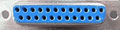
| Amiga | TV | ||
|---|---|---|---|
| Analog Red | 3 | 15 | RGB Red In |
| Analog Green | 4 | 11 | RGB Green In |
| Analog Blue | 5 | 7 | RGB Blue In |
| Composite Sync | 10 | 20 | Composite Video In |
| Analog Red GND | 16 | 13 | RGB Red In GND |
| Analog Green GND | 17 | 9 | RGB Green In GND |
| Analog Blue GND | 18 | 5 | RGB Blue In GND |
| Composite Sync GND | 19 | 18 | Composite Video In GND |
| Video GND | 20 | 21 | AV Select GND |
| Video GND | 20 | 14 | RGB enable GND |
| +5V | 23 | 16 | RGB enable (Connect via ~110 Ohm resistor to produce 1-3v) |
| +12V | 22 | 8 | AV Select / 4:3 Aspect ratio |
| Phono Right | 2 | Audio IN Right | |
| Phono Right GND | 4 | GND | |
| Phono Left | 6 | Audio IN Left | |
| Phono Left GND | 4 | GND |
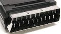
audio or video connector or cable

 correct
 incorrect