
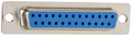
| Pin | Name | Dir | Description |
|---|---|---|---|
| 1 | +12V | +12 VDC | |
| 2 | +5V | +5 VDC | |
| 3 | +5V | +5 VDC | |
| 4 | /INDEX | Sector hole passed sensor. | |
| 5 | /DSEL1 | Drive Select 1 | |
| 6 | DIR | Direction (0=In, 1=Dir) | |
| 7 | /STEP | Moves head 1 step in DIR direction. | |
| 8 | WRITEDATA | Write Data | |
| 9 | /WRITEGATE | Write Gate | |
| 10 | /TRACK00 | Head is over Track 00 (outermost track) | |
| 11 | /WRITEPROTECT | Write protected disk (0=Write protected) | |
| 12 | READDATA | Data read from diskette. | |
| 13 | /SIDESELECT | Side Select (0=Side 1, 1=Side 0) | |
| 14 | +12V | +12 VDC | |
| 15 | +12V | +12 VDC | |
| 16 | +5V | +5 VDC | |
| 17 | /DSEL0 | Select Drive 0 | |
| 18 | /MOTOR | Motor On | |
| 19 | READY | Ready | |
| 20 | GND | Ground | |
| 21 | GND | Ground | |
| 22 | GND | Ground | |
| 23 | GND | Ground | |
| 24 | GND | Ground | |
| 25 | GND | Ground |
 correct
 incorrect
If you did publish instruction for Do-It-Yourself device with this pinout, share the link with us.