
| Pin | Name | Dir | Description |
|---|---|---|---|
| 2 | /REDWC |  |
Reduced Write Current |
| 4 | n/c | - | Reserved |
| 6 | n/c | - | Reserved |
| 8 | n/c | - | Reserved |
| 10 | /FD2S |  |
Disk is two sided |
| 12 | /DCG | |
Disk has been changed/door open |
| 14 | /SIDE | |
Side select |
| 16 | /DLOCK | |
Door lock |
| 18 | /HLD | |
Head load |
| 20 | /INDEX | |
Index Pulse |
| 22 | /READY | |
Ready |
| 24 | n/c | - | Not connected |
| 26 | /SEL1 | |
Select Drive 1 |
| 28 | /SEL2 | |
Select Drive 2 |
| 30 | /SEL3 | |
Select Drive 3 |
| 32 | /SEL4 | |
Select Drive 4 |
| 34 | /DIR | |
Direction |
| 36 | /STEP | |
Step |
| 38 | /WDAT | |
Write data |
| 40 | /WGAT | |
Write gate |
| 42 | /TR00 | |
Track 00 (Zero) |
| 44 | /WPROT | |
Write protect |
| 46 | /RDATA | |
Read data |
| 48 | n/c | - | Not connected |
| 50 | n/c | - | Not connected |
Note: Direction is Computer relative Diskdrive.
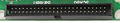
Note: All odd pins are GND, Ground.
Pinout matches Radio SHack Model II FDC (except the Model II doesn't use DLOCK Pin 16.
 correct
 incorrect