
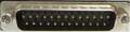
| Pin | Name | Dir | Description |
|---|---|---|---|
| 1 | /STROBE | Strobe | |
| 2 | D0 | Data Bit 0 | |
| 3 | D1 | Data Bit 1 | |
| 4 | D2 | Data Bit 2 | |
| 5 | D3 | Data Bit 3 | |
| 6 | D4 | Data Bit 4 | |
| 7 | D5 | Data Bit 5 | |
| 8 | D6 | Data Bit 6 | |
| 9 | D7 | Data Bit 7 | |
| 10 | /ACK | Acknowledge | |
| 11 | BUSY | Busy | |
| 12 | POUT | Paper Out | |
| 13 | SEL | Select (Shared with RS232 RING-indicator) | |
| 14 | GND | Signal Ground | |
| 15 | GND | Signal Ground | |
| 16 | GND | Signal Ground | |
| 17 | GND | Signal Ground | |
| 18 | GND | Signal Ground | |
| 19 | GND | Signal Ground | |
| 20 | GND | Signal Ground | |
| 21 | GND | Signal Ground | |
| 22 | GND | Signal Ground | |
| 23 | +5V | +5 Volts DC (10 mA max) | |
| 24 | n/c | - | Not connected. |
| 25 | /RESET | Reset |
 правильная
 с ошибками
Если вы знаете как сделать самодельное устройство с использованием этой распиновки, отправьте нам ссылку на описание.