Obsolete hardware connectors pinouts

Atari Paddle Controller pinout

connector or cable wiring scheme

bookmark this page

Atari Paddle controller DE-9 pinout

The Paddles are just two Potentiometers with a push swtich in a plastic shell. The analogue controls use unused pins from the Atari joystick while the buttons use the left and right ones. The Pots share the same VCC while outputting the current through their own respective pins. They can be hooked up to an Atari 2600 with a joystick connected to the same DE-9 port and not interfere with the joystick, aside from the buttons using Left and Right.
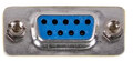
Pin
Number
Pin
Name
Description (may be empty)
1 N/A  Not connected
2 N/A  Not connected
3 P1B  Paddle 1 Button
4 P2B  Paddle 2 Button 
5 P2O  Paddle 2 Pot Output
6 N/A  Not connected
7 VCC  VCC for Pots
8 GND  Ground for Buttons
9 P1O  Paddle 1 Pot Output


Is there anything to be corrected? Edit this page!
9 pin D-SUB male connector layout
9 pin D-SUB male connector
at the Atari 2600
Contributor(s): Naoki Saito
This information should be correct, but we are not sure.
Is this document CORRECT or INCORRECT?.
Pinouts.ru >  Input devices (keyboards, mices, joysticks) pinouts >  Pinout of Atari Paddle Controller. Is this document correct or incorrect?
Is it correct?:
unknown
no visitors comments
Last updated 2011-08-10 16:14:47. Edit this page.
[Discuss at the forum] [Back to index] [SUBMIT new pinout]
This page contain parts under Copyright © 2000-2010 by pinouts.ru team.
No portion of this webpage may be reproduced in any form without providing visible HTML link to pinouts.ru . Webmaster permission required in any other cases.
Efforts have been made to ensure this page is correct, but it is the responsibility of the user to verify the data is correct for their application.
[an error occurred while processing this directive]