

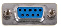
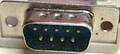
| Pin | Color | Dir | Description |
|---|---|---|---|
| 1 | WHT |  |
Up |
| 2 | BLU | |
Down |
| 3 | GRN | |
Left |
| 4 | BRN | |
Right |
| 5 | RED | |
Button (R)ight (-) |
| 6 | ORG | ? | Both buttons (+) |
| 7 | +5V | - | +5v, needs to be connected for the 7800 joystick to function correctly |
| 8 | BLK | Ground(-) | |
| 9 | YLW | |
Button (L)eft (-) |
Note: Direction is Computer relative Device.
C116,C16 and +4 joystick ports are mini-DIN, not DE-9.

 correct
 incorrect