

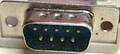
Control Port 1
| Pin | Name | Dir | Comment |
|---|---|---|---|
| 1 | JOYA0 | UP | |
| 2 | JOYA1 | DOWN | |
| 3 | JOYA2 | LEFT | |
| 4 | JOYA4 | RIGHT | |
| 5 | POT AY | ||
| 6 | BUTTON A/LP | FIRE | |
| 7 | +5V | 50 mA max | |
| 8 | GND | ||
| 9 | POT AX |
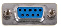
Control Port 2
| Pin | Name | Dir | Comment |
|---|---|---|---|
| 1 | JOYB0 | UP | |
| 2 | JOYB1 | DOWN | |
| 3 | JOYB2 | LEFT | |
| 4 | JOYB4 | RIGHT | |
| 5 | POT BY | ||
| 6 | BUTTON B | FIRE | |
| 7 | +5V | 50 mA max | |
| 8 | GND | ||
| 9 | POT BX |

 correct
 incorrect