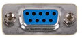
| Pin | Mouse | Joystick | Dir | Comment |
|---|---|---|---|---|
| 1 | XB | UP | ||
| 2 | XA | DOWN | ||
| 3 | YA | LEFT | ||
| 4 | YB | RIGHT | ||
| 5 | n/c | n/c | - | |
| 6 | LEFTBUTTON | FIRE | ||
| 7 | +5V | +5V | ||
| 8 | GND | GND | ||
| 9 | RIGHTBUTTON | res |
 correct
 incorrect
If you did publish instruction for Do-It-Yourself device with this pinout, share the link with us.
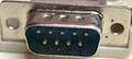
| Pin | Mouse | Joystick | Dir | Comment |
|---|---|---|---|---|
| 1 | XB | UP | ||
| 2 | XA | DOWN | ||
| 3 | YA | LEFT | ||
| 4 | YB | RIGHT | ||
| 5 | n/c | n/c | - | |
| 6 | LEFTBUTTON | FIRE | ||
| 7 | +5V | +5V | ||
| 8 | GND | GND | ||
| 9 | RIGHTBUTTON | res |