
Each drive has each own data cable. By twisting some wires on the control cable it wont be necessary to set the ID for each drive, since the twist will do the job. Wires 25 to 29 should be twisted between drive 1 & drive 2.
Controller           Drive 2   Twist   Drive 1

+--+                   +--+            +--+

|::|===================|  |============|  |  <-Pin 1
|::|===================| |============| |
|::|===================| |============| |
|::|===================| |============| |
|::|===================| |=====/=====| |
|::|===================| |=====/=====| |
|::|===================| |============| |
+--+ +--+ +--+
| Controller | Drive 1 | Drive 2 | |
|---|---|---|---|
| Wire 1-24 | 1-9 | 1-9 | 1-9 |
| Wire 25 | 25 | 29 | 25 |
| Wire 26 | 26 | 28 | 26 |
| Wire 27 | 27 | 27 | 27 |
| Wire 28 | 28 | 26 | 28 |
| Wire 29 | 29 | 25 | 29 |
| Wire 30-34 | 30-34 | 30-34 | 30-34 |
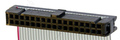
Data cable
 (To the Controller)
(To the Drive)
20 PIN IDC FEMALE to the Controller.
20 PIN IDC FEMALE to the Drive.
| Controller | Drive | |
|---|---|---|
| Wire 1-20 | 1-20 | 1-20 |
 correct
 incorrect