
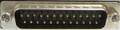
| Pin | Name | Dir | Description |
|---|---|---|---|
| 1 | SHIELD | Shield Ground | |
| 2 | TXD | Transmit Data | |
| 3 | RXD | Receive Data | |
| 4 | RTS | Request to Send | |
| 5 | CTS | Clear to Send | |
| 6 | DSR | Data Set Ready | |
| 7 | GND | System Ground | |
| 8 | CD | Carrier Detect | |
| 9 | n/c | - | |
| 10 | n/c | - | |
| 11 | n/c | - | |
| 12 | n/c | - | |
| 13 | n/c | - | |
| 14 | -5V | -5 Volts DC (50mA max) | |
| 15 | AUDO | Amiga Audio Out (Left) | |
| 16 | AUDI | Amiga Audio In (Right) | |
| 17 | EB | - | EB=Buffered Port Clock 716 kHz |
| 18 | /INT2 | ? | Interrupt 2 |
| 19 | n/c | - | |
| 20 | DTR | Data Terminal Ready | |
| 21 | +5V | +5 Volts DC | |
| 22 | n/c | - | |
| 23 | +12V | +12 Volts DC (20 mA max) | |
| 24 | /C2 | C2=Clock 3.58MHz | |
| 25 | /RESET | Reset |
 правильная
 с ошибками
Если вы знаете как сделать самодельное устройство с использованием этой распиновки, отправьте нам ссылку на описание.