

Image of the connector here.
| Pin Number |
Pin Name |
Description |
|---|---|---|
| 1 | in: neutral | 100-240V AC |
| 2 | in: phase | 100-240V AC |
| 3 | in: earth | 100-240V AC (connected to chassis) |
| 4 | out: 12V | 45A max (for all 12V added) |
| 5 | out: 12V | 45A max (for all 12V added) |
| 6 | out: GND | |
| 7 | out: GND | |
| 8 | 4 x 6 pin matrix | the 2 bottom right pins must be connected to GND to be on |
| 9 | out: GND | |
| 10 | out: GND | |
| 11 | out: GND | |
| 12 | out: 5V | 28A max (for all 5V added) |
| 13 | out: 3.3V | 50A max (for all 3.3V added) |
| 14 | out: 3.3V | 50A max (for all 3.3V added) |
 correct
 incorrect
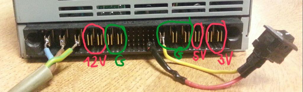