

| Pin Number |
Pin Name |
Description |
|---|---|---|
| 1 | MIC | Front panel microphone input signal (biased when supporting stereo microphone) |
| 2 | AUD_GND | Ground used by analog audio circuits |
| 3 | MIC_BIAS | Microphone power / additional MIC input for stereo microphone support |
| 4 | AUD_GND | Ground used by analog audio circuits |
| 5 | FP_OUT_R | Right channel audio signal to front panel (headphone drive capable) |
| 6 | FP_RETURN_R | Right channel audio signal return from front panel (when headphones unplugged) |
| 7 | AUD_5V | Filtered +5 V used by analog audio circuits |
| 8 | KEY | No pin |
| 9 | FP_OUT_L | Left channel audio signal to front panel (headphone drive capable) |
| 10 | FP_RETURN_L | Left channel audio signal return from front panel (when headphones unplugged) |
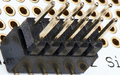
The rear panel audio output jacks are disabled when headphones are plugged in. This feature is implemented through the front panel audio header shown in Figure 3 and Table 6. If the front panel interface board is not connected to the front panel audio header, jumpers should be installed across header pin pairs 1-2, 3-4, 5-6, and 9-10. If these jumpers are not installed, the rear panel line out connector will be inoperative and microphone input pins 1 and 3 will be left floating, which could lead to elevated back panel microphone noise and cross talk.
 correct
 incorrect