
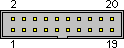
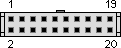
| Pin Number |
Pin Name |
Description |
| 1 | GND | System ground/shielding |
| 2 | A4 | Row/address line |
| 3 | A0 | Row/address line |
| 4 | A3 | Row/address line |
| 5 | A6 | Row/address line |
| 6 | A2 | Row/address line |
| 7 | A5 | Row/address line |
| 8 | A1 | Row/address line |
| 9 | A7 | Row/address line |
| 10 | D0 | Column/data line |
| 11 | D1 | Column/data line |
| 12 | D2 | Column/data line |
| 13 | D3 | Column/data line |
| 14 | D4 | Column/data line |
| 15 | D5 | Column/data line |
| 16 | D6 | Column/data line |
| 17 | D7 | Column/data line |
| 18 | NC | Exists in cable, not connected at either end |
| 19 | +12V | Connected on PCB, not in cable |
| 20 | GND | System ground/shielding |
Pin 1 is towards the top-right when looking at the front of the computer in the usual fashion. On the later '1a' model which I have, the plug on the coiled keyboard cable actually has 24 holes but the outer 4 do not mate with pins (it's not quite the same plug you find on a ribbon cable).
The Osborne 1 keyboard contains no electronics and does not require a power supply. The row and column lines connect directly to a matrix of keys. I believe that to read a row, the address is selected such that exactly one of the row outputs is driven low. Any pressed keys in that row will cause a zero to be read on the respective column line, while other column lines will be pulled up.
Pins 2-9 are driven by the system address bus through open-collector inverters. Pins 10-17 are pulled up to the system +5V supply by a 3.3K resistor pack, and buffered onto the system data bus when the processor reads the keyboard.
Pin 19 can be connected to the system +12V supply through J6 (a 2-pin link, open on my Rev. D PCB) and R21 (22 ohms).
I'm intending to build a PS/2 keyboard adapter using an ATtiny and a bunch of 74LS374's, as my keyboard was busted when I got it (eBay bargain).
| D0 | D1 | D2 | D3 | D4 | D5 | D6 | D7 | |
| A0 | Esc | Tab | Ctrl | Shift | Return | ' | [ ] | |
| A1 | 1 ! | 2 @ | 3 £ | 4 $ | 5 % | 6 ^ | 7 & | 8 * |
| A5 | Up | Left | 0 ) | Space | . > | P | O | 9 ( |
| A2 | Q | W | E | R | T | Y | U | I |
| A3 | A | S | D | F | G | H | J | K |
| A4 | Z | X | C | V | B | N | M | , < |
| A6 | Right | Down | - _ | / ? | ; : | \ | | L | = + |
| A7 | Lock |
 правильная
 с ошибками