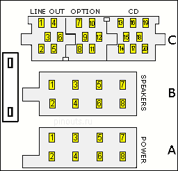
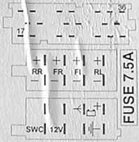
Head unit pinout abbreviations
| Pin Notation |
Pin function |
|---|---|
Power pins |
|
| B+ | Battery+ (12V direct from Battery). |
| GND, GROUND | Chassis Ground |
| A+ | Ignition powered. +12 V with the ignition key is in the ACC or ON position. |
| lightbulb image | Light-on signal or backlight adjustment. +12V supplied to light-on pin of head unit when tail lights ar turned on. |
| ANT+, P.ANT, ANT | Power for Electric Antenna. Output +12 V (maximum 150 - 300mA) |
Audio pins |
|
| FR+ or RF+ | Front right speaker out |
| FL+ or LF+ | Front left speaker out |
| RR+ | Rear right speaker out |
| LR+ or RL+ | Rear left speaker out |
| FR- or RF-, FL- or LF-, RR-, LR- or RL-, SGND | The corresponding speaker ground |
Misc. pins |
|
| Mut | This pin is used to silence the audio, earthed by some other external components that is connected to the radio. |
| SDV | This pin is used in some radio equipment to automatically boost up the volume. It needs the output from the speed sensor. |
| SDA, SCL, MRQ | Head unit communication (information display and so on) |


 correct
 incorrect