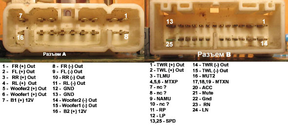
Head unit pinout signals explained
| Pin Notation |
Pin function |
|---|---|
Power pins |
|
| BU, +B | Battery+ (12V direct from Battery). |
| GND, GROUND, SLD1 | Chassis Ground |
| ACC | Ignition powered. +12 V with the ignition key is in the ACC or ON position. |
| ILL | Light-on signal or backlight adjustment. +12V supplied to light-on pin of head unit when tail lights ar turned on. May be used for backlight adjustment in some models. |
| ANT | Power for Electric Antenna. Output +12 V (maximum 150 - 300mA) |
Audio pins |
|
| FR+ or RF+ | Front right speaker out |
| FL+ or LF+ | Front left speaker out |
| RR+ | Rear right speaker out |
| LR+ or RL+ | Rear left speaker out |
| FR- or RF-, FL- or LF-, RR-, LR- or RL-, SGND | The corresponding speaker ground |
Misc. pins |
|
| MUTE | This pin is used to silence the audio, earthed by some other external components that is connected to the radio. |
| Amp | Amplifier control |
| RSR+.RSR-,RSL+, RSL- | Audio Signal to Rear Audio Controller, For Wireless Headphones |
| TX+, TX- | Display communication?? |
| SW1 | Seek+/-, Vol+/- Inputs from Steering wheel audio controls |
| SW2 | Mode input from Steering wheel audio controls |
| RMU | Mute Signal to Rear Audio Controller, Logical 1 when Radio Switch is On |


 correct
 incorrect