
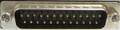
| Pin | Name | Dir | Description |
|---|---|---|---|
| 1 | SHIELD | Shield Ground | |
| 2 | TXD | Transmit Data | |
| 3 | RXD | Receive Data | |
| 4 | RTS | Request to Send | |
| 5 | CTS | Clear to Send | |
| 6 | DSR | Data Set Ready | |
| 7 | GND | System Ground | |
| 8 | CD | Carrier Detect | |
| 9 | +12V | +12 Volts DC (20 mA max) | |
| 10 | -12V | -12 Volts DC (20 mA max) | |
| 11 | AUDO | Amiga Audio Out (Left) | |
| 12 | n/c | - | Speed Indicate |
| 13 | n/c | - | |
| 14 | n/c | - | |
| 15 | n/c | - | |
| 16 | n/c | - | |
| 17 | n/c | - | |
| 18 | AUDI | Amiga Audio In (Right) | |
| 19 | n/c | - | |
| 20 | DTR | Data Terminal Ready | |
| 21 | n/c | - | |
| 22 | RI | Ring Indicator | |
| 23 | n/c | - | |
| 24 | n/c | - | |
| 25 | n/c | - |
 correct
 incorrect
If you did publish instruction for Do-It-Yourself device with this pinout, share the link with us.